
Digital filters
What Is a Digital Filter?
A digital filter is a signal processing technique for removing unwanted noise from a signal or extracting only specific frequency components. PLC analog input values often contain noise, and low-pass or notch filters make stable control and measurement possible.
Overview
This page introduces digital filter sample programs
that can be used on the OMRON NX/NJ series.
To remove noise from analog inputs
and extract specific frequency components,
low-pass filters (LPF),
high-pass filters (HPF),
band-pass filters (BPF),
notch filters and more
are implemented as function blocks.
The operating waveforms of each filter and the sample programs are provided,
so use them as a reference for signal processing and analog data analysis on PLCs.
Creates simple digital filters
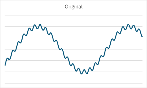
Original waveform
The original waveform contains a 30 Hz sine wave with 500 Hz noise
We apply the following 8 types of filters
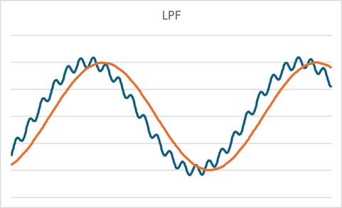
Low-pass filter
Cuts off frequencies above 100 Hz to remove noise
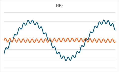
High-pass filter
Cuts off frequencies below 100 Hz to remove noise
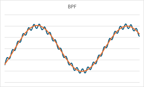
Band-pass filter
Passes one octave of frequencies around 30 Hz
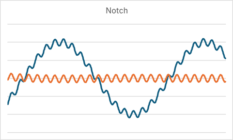
Notch filter
Removes one octave of frequencies around 30 Hz
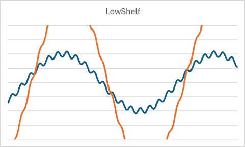
Low-shelf filter
Amplifies frequencies below 100 Hz
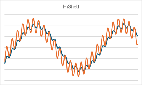
High-shelf filter
Amplifies frequencies above 100 Hz
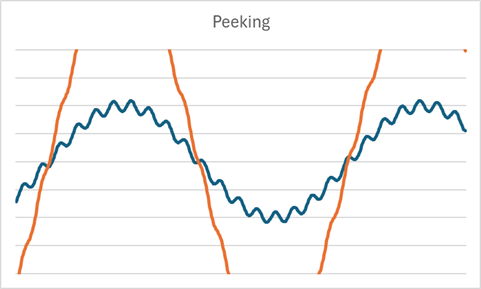
Peaking filter
Amplifies one octave of frequencies around 30 Hz
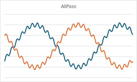
All-pass filter
Shifts the phase around the cutoff frequency
Symbols
Input/output variables common to all functions
- buf
- Stores the inputs and outputs from two samples ago (always assign a variable and do not use it outside the FB)
- In
- Input value
- SampFreq
- Sampling frequency
- Freq
- Cutoff frequency
- BandWidth
- Bandwidth
- gain
- Gain
- Result
- Result
The sampling frequency defaults to the task period of the executing task; for high-speed analog units that acquire multiple analog values per scan, enter the sampling frequency (Hz) according to the setting
The graphs below show a 30 Hz + 500 Hz waveform collected at a sampling frequency of 10000 Hz and passed through the filters
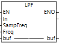
LPF (low-pass filter)
A filter that passes frequencies below the cutoff frequency
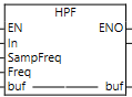
HPF (high-pass filter)
A filter that passes frequencies above the cutoff frequency
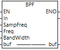
BPF (band-pass filter)
A filter that passes only the bandwidth around the cutoff frequency
With a cutoff frequency of 30 Hz and a bandwidth of 1 octave, the range is 30/2 to 30x2, so 15 Hz to 60 Hz is passed
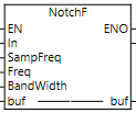
NotchF (notch filter)
A filter that passes everything except the bandwidth around the cutoff frequency
The opposite of BPF, it passes everything except 15 Hz to 60 Hz
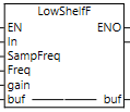
LowShelfF (low-shelf filter)
A filter that amplifies frequencies below the cutoff frequency by the specified gain
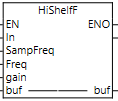
HiShelfF (high-shelf filter)
A filter that amplifies frequencies above the cutoff frequency by the specified gain
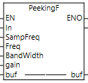
PeekingF (peaking filter)
A filter that amplifies the bandwidth centered on the cutoff frequency by the specified gain
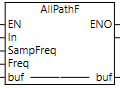
AllPassF (all-pass filter)
A filter that changes only the phase around the cutoff frequency
Example
Ladder logic
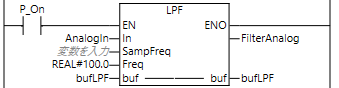
Applies a filter that passes only frequencies of 100 Hz or less to the AnalogIn data and outputs it to FilterAnalog
Source
Low-pass filter (LPF)
As an example, the low-pass filter is calculated as follows

